Magnet pull needed to hold 230g phone in 3mm case

Determine the magnet pull force needed to hold a 230g phone in a 3mm case on a 32mm vertical tube during deadlifts without falling, including a calculation method, assumptions, and guidance
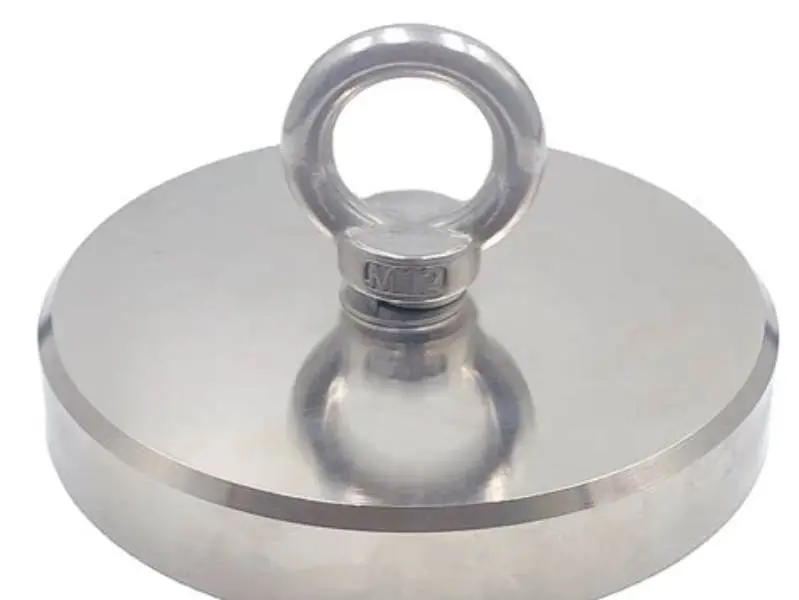
A practical target is a magnet pull rating of about 8–12 N for a 230 g phone in a 3 mm plastic case on a 32 mm vertical tube during typical deadlift motions. This range is a consolidated recommendation based on a simple physics calculation (mass × [gravity + peak acceleration]) combined with likely coupling losses from a 3 mm gap and curved-surface contact. Verify with a pull-force meter and manufacturer pull charts for the specific magnet and case.
On this page (8 sections)
- Key takeaways
- How to calculate magnetic force required (formula and assumptions)
- Estimates and sources for accelerations during deadlifts
- How a 3 mm phone case and an air gap affect magnet pull (datasheets and measurement)
- How tube curvature and magnet placement affect holding force (quantitative considerations)
- Selecting magnet grade and size to meet the required pull
- Consolidated recommendation for a 230 g phone in a 3 mm case on a 32 mm tube during deadlifts
- Questions people still ask
Part of our guide on non-rotating mount for gym bar
| Phone mass | 230 g |
|---|---|
| Case thickness | 3 mm (plastic typical) |
| Tube diameter | 32 mm |
| Recommended magnet pull | 8–12 N (see method) |
| Acceleration estimate for deadlifts | peak vertical accelerations often in the 0–1 g extra range for controlled lifts; short transients can be higher (see sources) |
Key takeaways
- Calculate required holding force from mass and peak acceleration using F_required = m × (g + a_peak).
- Estimate magnet coupling efficiency for a 3 mm plastic case and curved 32 mm tube contact, then divide F_required by that efficiency to size the magnet.
- Manufacturers provide pull-force vs. gap charts; use those charts rather than assuming a fixed percent loss.
- A recommended target range for this setup is 8–12 N; measure your actual setup with a pull tester to confirm.
- Select magnet grade and size using manufacturer pull charts (common grades: N42–N52) and allow a safety margin for shocks and imperfect contact.
How to calculate magnetic force required (formula and assumptions)
Use a straightforward Newtonian approach: compute the maximum upward (or opposing) force the magnet must provide to prevent the phone from separating from the mount during peak motion. The vertical force the magnet must resist is the phone mass times the sum of gravitational acceleration and any peak upward acceleration during the lift: F_required = m × (g + a_peak).
Assumptions used in this guide: m = 0.230 kg (230 g phone); standard gravity g = 9.81 m/s²; a_peak is the peak upward acceleration of the phone relative to the bar during the motion (m/s²). a_peak depends on lift speed and technique; see the next section for discussion and references. The equation gives the vertical force that must be balanced to keep the phone from separating. If accelerations are downward (i.e., during descent), they reduce required force transiently, but lateral shocks or jerks can require additional lateral holding capability.
Magnets hold by normal (attractive) force, but practical magnetic mounting also depends on coupling efficiency η, which represents what fraction of the magnet's rated pull is available in your real configuration (air gaps from a case, non-ideal contact on a curved surface, intervening materials, etc.). To size a magnet: F_magnet_needed = F_required / η. Choose a safety factor (for example 1.25–2×) to cover unmodeled shocks and imperfect contact.
Worked numeric examples (showing how the 8–12 N recommendation arises): People in this spot often ask about suction cup size for 230g phone as well.
- Example A — moderate peak acceleration (a_peak = 0.5 g ≈ 4.9 m/s²): F_required = 0.230 × (9.81 + 4.9) ≈ 3.2 N. If coupling efficiency η = 0.6 (illustrative), F_magnet_needed ≈ 3.2 / 0.6 ≈ 5.3 N. With a safety factor of 1.5, specify ≈ 8 N.
- Example B — brisk lifting or a stronger transient (a_peak = 1.0 g ≈ 9.81 m/s²): F_required = 0.230 × (9.81 + 9.81) ≈ 4.5 N. With η = 0.6, F_magnet_needed ≈ 7.5 N. With a safety factor of 1.25–1.5, specify 9–11 N.
These examples demonstrate how the consolidated recommendation of 8–12 N follows from modest variations in assumed a_peak and coupling efficiency. Because η varies with case material, gap, and tube contact, measuring with a pull meter is the final check. The other half of this decision is magnet pull to hold phone during sets.
| Case | a_peak (m/s²) | F_required (N) = m(g + a) | Assumed η | F_magnet_needed (N) w/o safety factor | Recommended (with safety) |
|---|---|---|---|---|---|
| Moderate lift | 4.9 (≈0.5 g) | ≈3.2 | 0.6 | ≈5.3 | ≈8 |
| Brisk/rapid lift | 9.8 (≈1.0 g) | ≈4.5 | 0.6 | ≈7.5 | ≈10–11 |
| Rapid with contact imperfections | 9.8 (≈1.0 g) | ≈4.5 | 0.45 | ≈10 | ≈12 |
Estimates and sources for accelerations during deadlifts
Published experimental data on barbell kinematics and force plates indicate that peak bar accelerations during conventional deadlifts vary substantially with load, lifter intent, and phase of the lift. For many controlled rep deadlifts the additional peak upward acceleration experienced by the bar (and an attached phone) is typically on the order of 0–1 g (0–9.8 m/s²) above gravity during the initial upward drive and transition phases; short transients larger than 1 g can occur during rapid attempts or jerks. Representative references and data sources include barbell kinematic studies and coaching biomechanics summaries (see references [1], [2]).
Because laboratory values depend on specific lifts and athletes, this guide uses the range 0.5–1.0 g for typical controlled to brisk lifting scenarios as a practical engineering assumption. Where precise numbers matter, measure the acceleration directly with an accelerometer attached to the phone or bar and use that measured a_peak in the formula above.
How a 3 mm phone case and an air gap affect magnet pull (datasheets and measurement)
Magnet pull ratings provided by manufacturers are normally specified for direct, flat contact (zero gap) to a clean steel surface. Any nonmagnetic gap (such as a 3 mm plastic phone case) reduces the effective pull considerably because magnetic field strength and flux linkage fall rapidly with distance. Manufacturer pull vs. gap charts are the reliable source for quantifying this effect for a given magnet geometry and grade. For example, many neodymium disk magnets show a steep drop in pull force with increasing separation in the millimeter range; see typical manufacturer data in references [3], [4]. We cover magnet force needed for rugged case phone in its own article.
Rather than adopting a single fixed percentage loss, use the magnet's pull vs. gap curve to find η_case = pull_at_gap / pull_at_contact. As a practical range for common small neodymium discs and a 3 mm nonmagnetic gap, η_case often falls in the 0.5–0.7 range (i.e., a 30–50% reduction in available pull compared to contact), but the exact value depends on magnet diameter, thickness, and grade. The datasheet is authoritative for each magnet size/grade; if the datasheet does not include your exact gap, measure with a pull tester for your phone+case assembly.
Recommendation: consult manufacturer pull charts (examples in references [3], [4]) and, if possible, measure your actual phone+case on the selected magnet using a pull-force gauge.
- Always check magnet pull vs. gap curves on the manufacturer's datasheet.
- For small magnets, a few millimetres of nonmagnetic separation can sharply reduce pull; measure for your exact configuration.
- If manufacturer data are unavailable for your gap, perform a direct pull test with the phone in its case.
How tube curvature and magnet placement affect holding force (quantitative considerations)
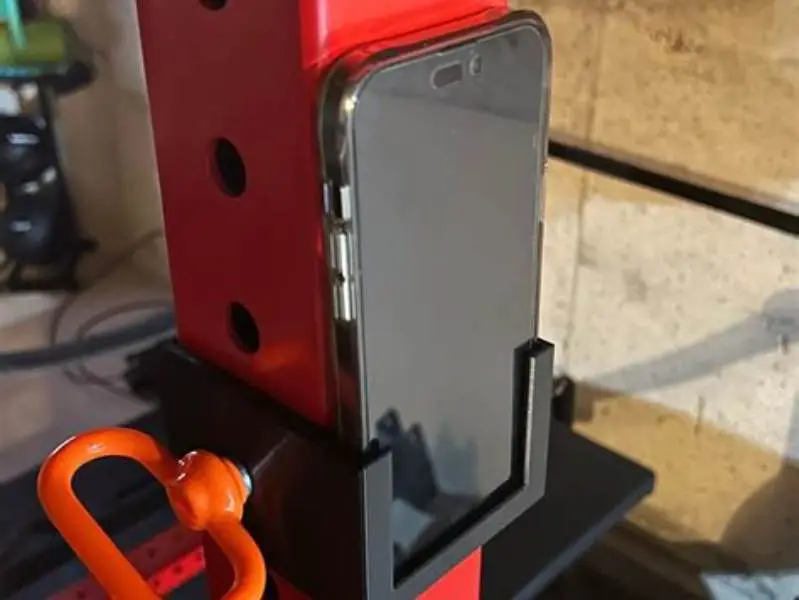
A flat magnet pressed to a cylindrical bar will have reduced contact area versus a flat plate. The amount of contact—and therefore effective pull—depends on the magnet diameter relative to the tube radius (R = 16 mm for a 32 mm tube) and magnet thickness. Smaller-diameter magnets conform less to curvature and lose more contact area. For the detail, see our notes on phone mount for pixel 7 pro curved tube.
A useful approximation: for a rigid circular magnet of diameter d on a cylinder of radius R, the contact width along the magnet edge can be estimated from the geometry of two circles. The greater the ratio d/(2R), the better the contact. When d is small relative to 2R, the real contact becomes a narrow strip, reducing effective flux coupling. This geometric loss is in addition to any gap from a case.
Manufacturer notes and practical tests often show curvature-related reductions in available pull on the order of 10–25% for small flat magnets on a 32 mm tube compared to ideal flat-surface contact, but the exact reduction varies with magnet diameter and how well the mount compensates (magnet housing, conformal backing, or curved magnet types). For quantitative assessment, either:
- consult a magnet vendor's technical guidance for curved-surface mounting (some vendors provide contact/curvature data), or
- measure the pull on the tube directly with the phone in its case and the magnet mounted in the intended position.
If using multiple magnets or a molded mount that matches the tube curvature, curvature losses can be reduced substantially.
- 32 mm tube curvature reduces contact area; effect scales with magnet diameter.
- Typical practical reduction: roughly 10–25% compared to flat contact for small disks, depending on magnet size.
- Use curved mounts or multiple magnets to recover contact area and reduce losses.
Selecting magnet grade and size to meet the required pull
Magnet grade (e.g., N35, N42, N52) indicates the material's maximum energy product; higher grades provide stronger fields for the same size. For small, compact mounts, N42–N52 are common choices because they give high pull per unit volume.
Manufacturers publish pull-force charts for specific magnet diameters and thicknesses. The practical selection process is:
1) Calculate F_required from mass and an estimate or measurement of a_peak. 2) Decide on a target coupling efficiency η (based on case gap and tube contact); when in doubt use a conservative η = 0.45–0.6 for a 3 mm plastic case on a curved bar. 3) Compute F_magnet_needed = F_required / η and apply a safety factor (1.25–1.5). 4) Use manufacturer pull charts to choose a magnet geometry and grade whose zero-gap rated pull meets or exceeds that F_magnet_needed. 5) If necessary, select a larger diameter or thicker magnet or use multiple magnets.
Practical notes: a small diameter, thin disc may have modest zero-gap pull (often a few newtons). Increasing diameter or thickness raises zero-gap pull; moving to a higher grade (e.g., N52) also increases pull for the same geometry. If the magnet datasheet lists pull at specific gaps, pick the magnet with reported pull ≥ F_magnet_needed at the actual gap (3 mm) if available.
- Use N42–N52 grades for compact, strong mounts (check datasheet for pull vs. gap).
- Choose a magnet size whose datasheet shows pull at your gap ≥ required magnet pull.
- Consider multiple magnets or a molded curved mount to improve contact and reduce required single-magnet size.
Consolidated recommendation for a 230 g phone in a 3 mm case on a 32 mm tube during deadlifts
Using the calculation method above and realistic assumptions for a typical lifter, a practical recommended magnet pull rating to specify is about 8–12 N. This single consolidated range covers moderate to brisk lifting with a 3 mm plastic case and the curved 32 mm tube when you allow a modest safety margin and expect some coupling loss from the case and curvature.
How that range maps to calculations: if peak upward acceleration is ~0.5–1.0 g, the vertical force to counter is ≈3.2–4.5 N. With a conservative coupling efficiency η in the 0.45–0.6 range to account for a 3 mm case and curved contact, required magnet pull before safety margin becomes roughly 7.5–10 N. Applying a safety factor of 1.25–1.5 yields the 8–12 N recommendation.
Do not treat 8 N as an absolute guarantee for every setup. The appropriate magnet for your situation depends on the exact magnet geometry and grade, the phone case material and any metallic or magnetic inserts, how well the magnet contacts the tube, and the peak accelerations you actually produce. Measure the effective holding force with the phone in its case on the tube using a pull meter to confirm safety.
| Condition | Assumed a_peak | Assumed η (case + curvature) | Recommended pull (N) |
|---|---|---|---|
| Controlled lift, good contact | ≈0.5 g | ≈0.6 | ≈8 N |
| Brisk lift, some curvature loss | ≈1.0 g | ≈0.5 | ≈10 N |
| Fast lift with poor contact or metal inserts | ≈1.0 g + shocks | ≈0.45 | ≈12 N |
Questions people still ask
How does case thickness affect magnet strength for holding phones?
A nonmagnetic case creates a gap that reduces the magnet’s effective pull. Quantify this using the magnet manufacturer's pull vs. gap chart or by measuring the phone-plus-case on the magnet; typical small magnets often show substantial loss over a few millimetres. For many small neodymium magnets and a 3 mm plastic gap, expect a coupling efficiency roughly in the 0.5–0.7 range, but confirm on the datasheet or by direct test (see references [3], [4]).
Can the shape of the gym tube reduce how well magnets hold?
Yes. A 32 mm round tube can reduce effective contact area for a flat magnet, which reduces pull. Typical practical reductions for small flat disks on a 32 mm tube are in the order of 10–25%, depending on magnet diameter and how well the mount conforms. Use curved mounts or larger-diameter magnets to improve contact, or measure pull on the tube directly.
Should I increase magnet strength for dynamic motion like deadlifts?
Yes. Size the magnet to withstand peak dynamic forces, not just static weight. Compute F_required = m × (g + a_peak), account for coupling efficiency η, and add a safety factor. If you do not know a_peak, measure with an accelerometer or use conservative assumptions (0.5–1.0 g) and verify with a pull test.
Is 8 newtons always enough magnet pull for a 230g phone?
8 N is a practical minimum for controlled lifts with reasonably good contact and an assumed coupling efficiency. For brisk lifts, imperfect contact, or metal inserts in the case, 10–12 N is safer. Always confirm with measurement for your specific phone, case, magnet, and mount.
How can I measure the actual magnet pull on my phone and case?
Use a magnetic pull force meter (handheld pull tester) to measure detachment force. Attach the magnet to the tube as intended, fix the phone in its case to the magnet, and use the pull gauge to measure the force required to detach the phone laterally or perpendicularly as appropriate. Compare the measured force to your calculated required force.