Which magnetic shield plates fit Qi2 pucks without blocking wireless charging

Magnetic shield plates that are compatible with Qi2 pucks are typically non-conductive ferrite-based materials or specially designed composite laminates that minimize eddy currents; compatibility depends on material, thickness, and patterning, so test in your setup or confirm manufacturer datasheets for Qi2 compatibility.
On this page (10 sections)
- Fit check
- Remember this
- How magnetic shield plates can affect Qi2 charging (background and standards context)
- Why specific numerical thresholds need testing and citation
- How to identify materials and designs that tend to work
- How to test shield plate compatibility in your setup (practical measurement)
- Sourcing compatible shield plates and what to ask vendors
- Practical recommendations and alternatives
- Who should not add a shield plate
- FAQ
Part of our guide on car mount holding phone in thick case

25PCS RFID Ferrite Sheet Antimagnetic Stickers (420x300x0.2mm
Offers thin ferrite sheets 0.2mm thick labeled as ferrite material suitable for wireless charge compatibility
Check it on Amazon
2PCS RFID Ferrite Shielding Sheet 200x300mm
Provides ferrite shielding sheets 0.5mm thick with explicit ferrite material and EMI absorber properties for
See the budget option| Product | power transfer in your setup (absolute watts | Verdict | |
|---|---|---|---|
| 25PCS RFID Ferrite Sheet Antimagnetic Stickers (420x300x0.2mm Glue) Generic | Thickness 0.2 mm ferrite sheet labeled for wireless charge compatibility | Meets it | View on Amazon |
| 2PCS RFID Ferrite Shielding Sheet 200x300mm XXKKUQSD | Thickness 0.5 mm ferrite sheet labeled for wireless charge compatibility | Meets it | View on Amazon |
Fast facts
- Typical useful shield thickness
- Often thin (sub-mm) ferrite layers, but varies by design — check datasheet
- Performance check
- Compare power (W) with/without plate in your setup; acceptability depends on your required charge rate
- Material to avoid
- Conductive ferromagnetic metals (unperforated iron/steel) unless explicitly specified as compatible
- Common compatible materials
- Ferrite composites, ferrite films, segmented ferrite laminates (vendor-dependent)
- How to verify
- Manufacturer datasheet, sample testing, or third-party test report
Remember this
- Compatibility depends on material and design (ferrite composites vs. conductive metals), not a single universal thickness limit.
- Many usable shield plates are thin ferrite composites or patterned ferrite laminates; always check manufacturer specs and test in your mount.
- Measure power transfer with and without the shield plate in your real mount geometry to confirm acceptable performance for your phone and case.
- Avoid plain conductive ferromagnetic metal plates unless the supplier explicitly states compatibility and provides test data for Qi2.
- Look for products labelled for wireless charging compatibility (Qi, MagSafe/Qi2 guidance) and consult datasheets for thickness and material details.
How magnetic shield plates can affect Qi2 charging (background and standards context)
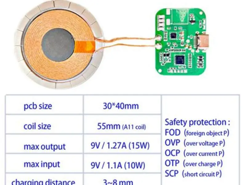
Qi2 wireless charging (a set of updates to the Qi standard maintained by the Wireless Power Consortium, WPC) still relies on inductive and resonant magnetic coupling between a transmitter coil (the puck) and a receiver coil in the phone. The efficiency and safe operation of that transfer depend on coil alignment, spacing, and the magnetic environment between the coils.
Anything placed between transmitter and receiver that changes the magnetic path can reduce coupling efficiency or increase heating. Two broad physical effects are relevant: (1) magnetic materials with high permeability (like ferrites) concentrate and guide magnetic flux and can improve coupling if designed correctly; (2) electrically conductive materials (including many metals) allow induced currents (eddy currents) that generate opposing magnetic fields and dissipate energy as heat, reducing transfer efficiency. The balance between these effects depends on the exact material properties, thickness, and geometry.
Qi/Qi2 documents and industry application notes discuss allowable assembly tolerances for coil spacing and magnetics because real-world mounts add cases, plates, and air gaps. For general context, the WPC technical guidance and vendor application notes (e.g., from ferrite and component makers) highlight that designers must consider permeability, conductivity, and the physical gap when adding any interposing layer. For readers wanting the primary source, consult the Wireless Power Consortium’s Qi/Qi2 technical resources and component manufacturer application notes on ferrite shielding (examples: WPC Qi2 spec and ferrite supplier application notes).
Why specific numerical thresholds need testing and citation
Many online guides quote single values for a 'safe' shield thickness or an efficiency cutoff (for example, phrases like "≤ 1 mm works" or "80% efficiency threshold"). Those numbers can be useful as rules of thumb, but they are not universal. Material composition (permeability and conductivity), plate patterning (solid vs. slotted or segmented), the phone’s receiver coil sensitivity, and case thickness all affect real-world results. The other half of this decision is qi puck mount avoiding heat.
Where such numbers appear in this article they are offered as typical ranges observed in vendor literature or in independent accessory tests, not as absolute laws. If you need a definitive limit for your exact phone, case, and mount, you must either obtain a vendor’s test report that covers your configuration or run the straightforward measurement described in the testing section below.
References and application notes: For general engineering guidance, see the Wireless Power Consortium Qi/Qi2 documentation for transmitter and accessory interoperability recommendations, and look for ferrite supplier application notes (e.g., TDK, Murata, and LTE/EMI shielding documentation) that explain how ferrite films and patterned laminates behave in inductive charging fields. These sources describe why permeability and conductivity matter and include measurement methodologies.
25PCS RFID Ferrite Sheet Antimagnetic Stickers (420x300x0.2mm Glue)
Offers thin ferrite sheets 0.2mm thick labeled as ferrite material suitable for wireless charge compatibility trials.
How to identify materials and designs that tend to work
Instead of relying on a single thickness number, look for these material and design clues in product descriptions and datasheets: There is more on magnetic puck pull force ratings in a separate guide.
- Material keywords: ferrite, ferrite composite, ferrite ceramic, ferrite film, or non-conductive magnetic laminate. These indicate materials that concentrate magnetic flux without being highly conductive.
- Design keywords: segmented, slotted, perforated, laminate, multilayer. Those describe physical patterning or layering used to interrupt eddy current paths while preserving magnetic guidance.
- Explicit compatibility claims: any product marketed for "wireless charging compatible," "Qi/Qi2 compatible," or "MagSafe-compatible ferrite" usually has been designed with charging in mind; manufacturers often provide test notes or datasheet entries showing thickness and recommended spacing. It helps to understand checking for play in forks before going further.
- Datasheet numbers: check for permeability (relative µ) and electrical conductivity. High µ and low conductivity is the desired direction for ferrite shielding; the datasheet may also list recommended gap tolerances.
Examples of where to source such plates: accessory makers that supply MagSafe or wireless-car-mount accessories (brands that specialize in mounts and wireless accessories), electronics distributors that carry ferrite films and sheets, and dedicated mobile accessory suppliers. When buying online, search terms that narrow results include "ferrite shield film wireless charging," "ferrite composite magnetic plate Qi compatible," or "wireless charge ferrite sticker." Look for listings that include a datasheet or explicitly mention Qi or MagSafe compatibility.
2PCS RFID Ferrite Shielding Sheet 200x300mm
Provides ferrite shielding sheets 0.5mm thick with explicit ferrite material and EMI absorber properties for NFC/RFID and wireless charging compatibility.
- Size Μ=120 T: 0.5mm
Get your phone to stay put on Qi2 puck mounts without killing wireless charging—pick ferrite-based plates and verify with a quick power-and-temperature test.
How to test shield plate compatibility in your setup (practical measurement)
The most reliable approach is an A/B test in the actual mount situation (same puck, phone, case, and mount). Steps below show a minimal lab-style check you can do with inexpensive tools.
What you need: a Qi2-compatible puck/transmitter, the shield plate or sample adhesive, the phone (with the case you normally use), and a way to measure charging power. A consumer-friendly approach uses a phone with a charging readout (some phones show instantaneous charge watts in battery settings or a diagnostic app). For more exact results, use an inline USB power meter on the transmitter’s USB input or a bench wattmeter if you have one.
Test procedure:
1) Baseline: Mount the puck in its working position, place your phone (with case) in the normal orientation, and record steady-state charging power and surface temperatures after a few minutes of charging. Note whether the charger maintains full rate or throttles.
2) With plate: Install the shield plate in the intended position between puck and phone (or attached as the accessory would sit) and repeat the measurements in the same environmental conditions. Allow a few minutes for readings to stabilize.
3) Compare results: Look at change in delivered power (absolute watts or percent change), and observe temperature rise on puck, plate, and phone. A small drop in power may be acceptable depending on your needs; a large drop or increasing temperatures indicate incompatibility.
4) Durability: If the plate passes the static test, try a few cycles of mounting/unmounting and a short ride/drive test if applicable to see whether mechanical stress alters performance.
What counts as acceptable will vary. A commonly cited heuristic is tolerating a modest percent drop in power if the phone still charges reliably and temperatures remain safe; however, instead of a fixed universal cutoff, use the percentage that still meets your daily charging needs. Manufacturer test reports will often state the maximum acceptable impact for a particular accessory.
- Record baseline charging power and temperature with no plate in place.
- Install the shield plate and repeat measurements in the same configuration.
- Compare power and temperature; watch for charger throttling or thermal protection.
- If results are acceptable, test mechanical durability and repeated cycles.
Sourcing compatible shield plates and what to ask vendors
Where to buy: reputable mobile accessory brands that list "wireless charge compatible" or "Qi2/MagSafe-friendly" on product pages; electronics distributors that carry ferrite films and include datasheets (e.g., major component suppliers); and specialist mount manufacturers who sell accessory plates designed for their mounts.
What to ask the vendor or check on the product page/datasheet:
- Does the product include a datasheet with material composition (e.g., ferrite ceramic, ferrite composite) and thickness specification? If so, confirm whether permeability and conductivity values are listed.
- Has the maker published compatibility testing with wireless chargers (Qi or MagSafe/Qi2)? Request test conditions: transmitter model, phone model, coil gap, measured output power, and thermal behavior.
- Is the plate solid or patterned (cutouts/slots)? Patterning is often used deliberately to reduce eddy currents and can be a positive sign.
- Does the vendor recommend this plate for specific mounts or phones? Prefer products that target Qi/MagSafe accessory markets rather than generic metal plates sold for magnetic attachment.
If the vendor cannot provide meaningful specifications or test results and you cannot test quickly yourself, consider buying a small sample from a seller with a reasonable return policy.
Practical recommendations and alternatives
Start with thin ferrite films or composite stickers marketed for wireless charging. These are the lowest-risk first option because they are explicitly designed to be placed near charging coils.
If you need better mechanical grip and the thin film is insufficient, look for multilayer ferrite laminates or ferrite plates with designed slots/cutouts. These balance magnetic guidance with low eddy current losses.
Avoid generic steel or iron plates marketed merely as "metal" magnetic adapters unless the seller supplies compatibility data for wireless charging: many such plates will degrade charging performance and increase heat.
When in doubt, test: a small sample purchase and the simple baseline vs. plate power check described above will tell you whether the accessory meets your needs for grip and charging.
Who should not add a shield plate
If your current mount holds your phone reliably and does not interfere with charging, adding another plate may add complexity and possibly harm charging performance.
If you need the absolute maximum, fastest wireless charging your phone supports (and your phone’s receiver is optimized for that peak), note that any interposed layer has the potential to reduce peak power. In such cases, avoid adding plates unless explicitly tested for your configuration.
If your phone or case already includes magnetic or metal reinforcement, adding a plate without testing can increase interference rather than help.
Choose ferrite-based or patterned ferrite composite plates sold specifically for wireless charging; verify compatibility with vendor data or a simple in-situ test to confirm acceptable power and temperature behavior.
FAQ
Can a metal shield plate ever work with Qi2 pucks?
Some metal plates can be designed or patterned to reduce eddy currents (for example, very thin perforated metal or segmented designs), but plain unmodified ferromagnetic metal sheets commonly reduce charging efficiency and increase heat. Rely on vendor test data or your own measurements when a metal component is included.
How do I know if my shield plate is ferrite composite?
Look for product text containing 'ferrite', 'ferrite ceramic', 'ferrite composite', or 'ferrite film' and for a datasheet listing material properties. Ferrite sheets are typically dark and ceramic-like, magnetic but not metallic in feel. If the listing lacks detail, ask the seller for a datasheet.
Why does my phone get hot when charging on a mount with a shield plate?
Noticeable heating usually indicates induced losses (eddy currents) or misaligned coils that force the system to generate heat. Stop using the plate until you confirm material compatibility by testing power and temperature; heat is a sign of inefficiency and potential stress on components.
Is thickness the only factor in shield plate compatibility?
No. Composition (permeability and conductivity), patterning (slots/segments), and how the plate is positioned relative to coils all influence compatibility. Thickness is one variable among several.
Where can I find reliable test data or standards?
Start with the Wireless Power Consortium (WPC) Qi/Qi2 technical documents for standard interoperability guidance and consult ferrite/EMI component manufacturer application notes (e.g., leading ferrite suppliers) for material behavior in inductive charging fields. Product datasheets and third-party accessory reviews often provide practical test figures.